Applying
the ArcGIS Hydro Data Model, Part 2
CE 394K GIS in Water Resources
University of Texas at
Austin
Fall 2001
Prepared by: Reem Zoun, Kristina Schneider, Tim Whiteaker, and David Maidment
Covered in Part 1
· Introduction to the ArcGIS Hydro Data Model and ArcHydro Framework
· Objectives of the Exercise
· Computer and Data Requirements
· Procedure for the Assignment
1. View your data in ArcMap and ArcCatalog
2. Prepare your Data for Schema Application
A. Create Centerline
B. Create Waterbody
C. Create Network Junctions
D. Create Geodatabase and Import Data
E. Create Geometric Network
Covered in Part 2
A. Add Schema Creation Wizard to ArcCatalog
D. Set Properties of Feature Classes
A. Add the Arc Hydro Tools to ArcMap
II.
Calculate Length Downstream
III. Find Next Downstream Junction
This portion of the Arc Hydro exercise assumes that you’ve already prepared the data for schema application and you have available a set of prepared files in an ArcHydro geodatabase. This file is attached here as a point of departure for this portion of the exercise. Application of the Arc Hydro tools requires a completely connected geometric network, which the attached file ArcHydroPart2.zip contains. These are also stored in the LRC on /class/maidment/giswr2001/archydro.
These files are:
ArcHydroTools_v1_Beta2: a zip file that contains the ArcHydroTools.dll (may be hidden from view) and the Arc Hydro Tools documentation explaining what the tools are and how to use them
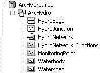
ArcHydro.mdb: the geodatabase you’ll use in this exercise (pictured below)
ArcHydroFrameworkSchema.mdb: the schema that will be applied this geodatabase
ArcHydroAfterSchema.mdb: the result of applying the schema (as a backup in case you have trouble with doing this)
ArcHydroAfterTools.mdb: the result of applying the ArcHydro tools (as a backup in case you have trouble with doing this)
This portion of the exercise also requires that you have available and have installed the Arc Hydro tools. The setup file for these tools can be obtained from the attached zip file. The tools should already be working in the computers in ECJ 3.400 but if you need to install them, simply run setup.exe in the attached zip file.
Ok, lets get started!!!
What you are beginning with is a draft ArcHydro.mdb database that looks like this:
3. Applying the Schema
A. Add the schema creation wizard to ArcCatalog
If the schema creation wizard ![]() has already been
added to ArcCatalog, skip to step 3.B, Connect to the Repository.
has already been
added to ArcCatalog, skip to step 3.B, Connect to the Repository.
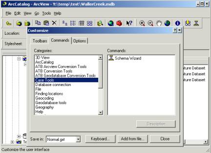
(1) Right click in the gray area in ArcCatalog where the buttons are and click Customize. You can also click Customize under the Tools menu.
(2) Click the Commands tab.
(3) If “Case Tools” appears in the categories list, skip to step (4) of this section. If “Case Tools” is not in the categories list, click “Add from file” and browse to the Bin directory where ArcGIS was installed (/arcexe81/bin). Select SchemaWiz.dll and click Open, then click OK. If you don’t see the SchemaWiz.dll in /arcexe/bin, it may still be there but invisible. Use Tools/Find File in Windows Explorer to locate the file, and then register the .dll using RegCat.exe, which is also located in /arcexe81/bin (This may also be invisible). Use Tools/Find File to locate RegCat.exe, right click on it and create a shortcut on your desktop. Drag the SchemaWiz.dll file onto the RegCat.exe shortcut and you’ll be prompted with a dialog to define where to register the .dll. Select ArcMap, ArcCatalog and ArcTools. Now, when you go to the Categories list you will see that the Case Tools option is available and the Schema Wizard icon is visible.
(4) Click “Case Tools” in the categories list.
(1) Drag the Schema Wizard command onto a toolbar.
(2) Click Close.
B. Connect to the Repository
(1) In the ArcCatalog tree, click the ArcHydro geodatabase to which you will apply the schema, so that it opens and you can see the feature dataset it contains.
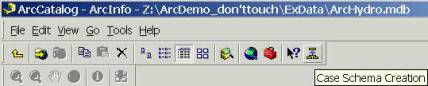
(2) Click the Case Schema Creation button to launch the Schema Creation Wizard. You may get a message saying that this action requires an ArcGIS or ArcEditor version of ArcGIS. In that event, go to Programs/ArcGIS/Desktop Administrator and set the seat to ArcGIS or ArcEditor.
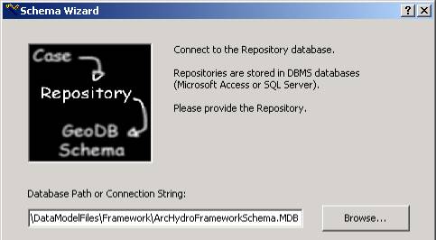
(3) Click Next to skip the introduction step, and then click Browse to select the repository database (in this exercise, ArcHydroFrameworkSchema.MDB). Ignore User Name and Password Requirement if asked for. Click Next to continue.
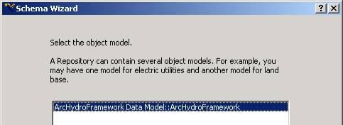
(4) Click the name of the object model in the repository for which you want to generate schema (ArcHydroFramework Data Model:: ArcHydroFramework).
(5) Click Next. This process may take a few minutes. A screen might appear asking you if you would like to use default values or values from a previous run. Select to use the default values. Press Next.
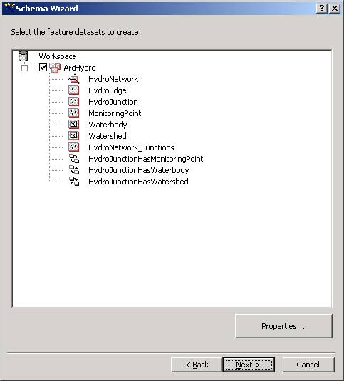
A tree-view of the schema represented in the model is displayed. Using this tree-view, you will now select the object classes (tables), feature datasets, and feature classes from your UML model for which you want to generate schema. The feature classes, highlighted with red, have been detected by the schema creation wizard since they have the correct Arc Hydro Framework name.
C. Select Feature Datasets
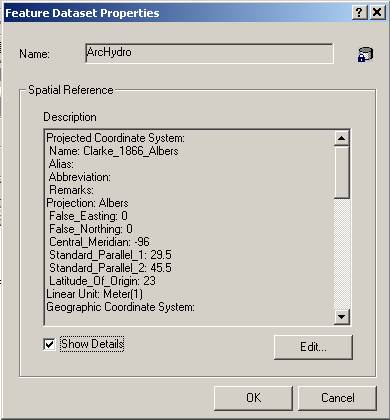
(1) Click on the ArcHydro feature dataset and then click Properties.
(2) On the Feature Dataset Properties window click Show Details to show the spatial reference information. Note that the spatial reference for that feature dataset has already been set (and that it coincides with the reference for the existing feature dataset).
(3) Click OK to close the properties window.
D. Set properties of feature classes
(4) Double Double-Click on “Watershed” and a dialog box for Watershed Properties will appear.
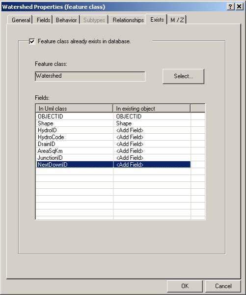
(5) Click on the Exists tab. Note near the top of the window that there is a check mark by “Feature class already exists in database” and the Watershed is listed in the Feature Class box. In this window you will match fields that were defined in the UML model to those that already exist in the Watershed feature class.
(6) In the “In existing object” column, click on “click to select” in the HydroID row. HydroID does not currently exist in the Watershed feature class; so select <Add Field> to add the field from the dropdown menu bar that is presented.
(7) Repeat step (6) for all unmatched UML classes.
Your Dialog box should look like this after you have matched all fields:
(8) Click OK and you will go back to Schema Wizard.
(9) Repeat steps 4, 5, 6, 7 & 8 for all feature classes in ArcHydro. You should have <Add Field> for any unmatched fields in all existing classes. Don’t worry about the HydroNetwork_Junctions class since it is empty and we don’t need it.
(10) Click OK to return to the Schema Wizard.
E. Create the schema
Once you have connected to the repository and selected the classes from your UML model for which you want to generate schema, the last part of the Schema Wizard is to actually create the schema in the geodatabase.
(1) Click Next.
At this point, you could review the options you specified in the Schema Wizard. If you wanted to change anything, you would click Back and change the appropriate parameters.
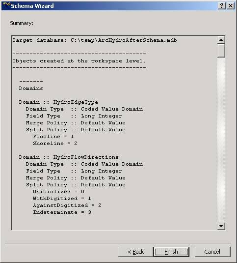
(2) Click Finish to generate the schema in the geodatabase. The generation may take a while. Say No to if you wanted to see the log file (or Yes if you wanted to see the log file!).
Congratulations! You have generated a schema!
View the feature classes that you’ve just worked on in ArcMap. Open the attribute tables and you’ll see that what you have done is to create a series of additional attributes at the right hand end of your attribute tables --- these are the standard Arc Hydro attributes.
To be turned in: Make a table that lists the five feature classes: HydroEdge, HydroJunction, MonitoringPoint, Waterbody and Watershed and list the attributes that were added to these feature classes by the process of applying the ArcHydro schema.
4. Applying Tools
A. Add the Arc Hydro Tools to ArcMap
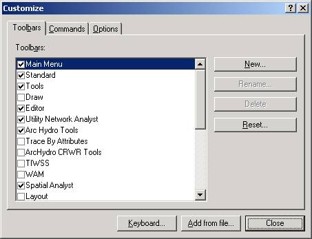
1. Right click in the gray area in ArcMap where the buttons are and click Customize. You can also click Customize under the Tools menu. Click the Toolbars tab.
2. If ‘Arc Hydro Tools’ appears in the toolbars list, skip to step 3 of this section. If ‘Arc Hydro Tools’ is not in the categories list, click “Add from file” and browse to the directory where the Arc Hydro Tools were installed (c:\Program Files\ESRI\ArcHydro\Bin by default). Select ArcHydroTools.dll and click Open, then click OK. The Arc Hydro Tools will appear on your Toolbars list now.
3. Click on the boxes for Editor, Utility Network Analyst and Arc Hydro Tools. You will need all three of these tools to apply the Arc Hydro Tools.
4. All three of the toolbars will appear on the screen. You can drag it onto the top of the screen or leave it floating. The Arc Hydro Tools toolbar looks like this:
![]()
5. Click Close to close the customize window.
B. Apply the Arc Hydro Tools
The Arc Hydro tools can determine values for Arc Hydro attributes.
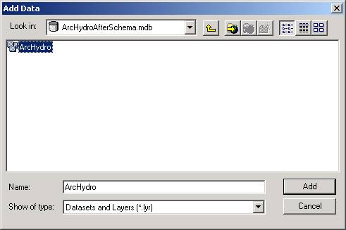
1. Add all of the feature classes in the ArcHydro feature dataset to ArcMap. You can do this by selecting the ArcHydro feature dataset and clicking Add, as shown below.
If you open the attribute tables of HydroJunction, you will find that the last few columns of the table is blank. We will use Arc Hydro Tools to calculate the values for some of these columns in HydroJunction and the other feature classes.
2. Go to View/Toolbars and click the Editor Toolbar on if it is not already active. On the Editor Toolbar click on Editor/Start editing.
I. Assign HydroID:
This tool assigns the HydroID values to the junctions and edges.
3. Right click on HydroJunction and Open Attribute Table for HydroJunction. You will find HydroID* column with <null> values in it.
4. In
the Attribute Tools menu of the Arc Hydro Tools toolbar, click on Assign
HydroID ![]() . A dialog box
appears with some options for assigning HydroID.
. A dialog box
appears with some options for assigning HydroID.
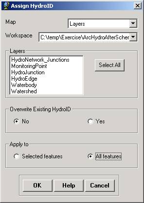
Click Select All to select all of the layers in the map. Then click OK. If prompted to save edits, click ‘Yes’. When the tool is finished, a message box appears displaying the range of HydroIDs that were assigned.
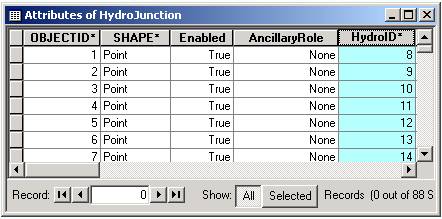
5. Open the attribute table of HydroJunction if necessary. You will find that the values of HydroID are now populated. The Assign HydroID tool has assigned HydroID values to all feature classes in the Arc Hydro Framework geodatabase. The HydroIDs begin with 1 and increment by 1 for each feature to which an ID is assigned. Each ID is unique within the geodatabase. See ‘Arc Hydro HydroID_v1.0 Beta2.doc’ in the ArcHydroTools_v1_Beta2.zip file for more information about the HydroID and how to customize it.
Your HydroJunction attribute table should look similar to this.
6. Close the attribute table.
II Calculate Length Downstream:
The Length Downstream Tool can calculate the downstream length from any junction or edge.
7. Save the ArcMap file and call it ‘Network_Tools’.
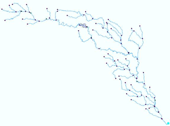
8. You will have to set the flow direction of edges in your network before you can apply the Calculate Length Downstream tool. Click on Editor/Start editing. Select the most downstream junction on your network as shown in the picture below:
9.
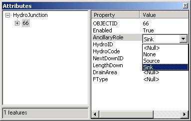
Click the Attributes ![]() button on the Editor
toolbar. The Attributes dialog box for the selected HydroJunction will appear.
Set the ancillary role of the selected junction to sink.
button on the Editor
toolbar. The Attributes dialog box for the selected HydroJunction will appear.
Set the ancillary role of the selected junction to sink.
10. Close the attributes dialog box.
11.
Click on the Set Flow Direction ![]() button.
button.
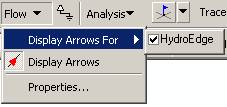
12. Go to Flow/Display Arrows For and click on the HydroEdge box. Click on Flow/Display Arrows.
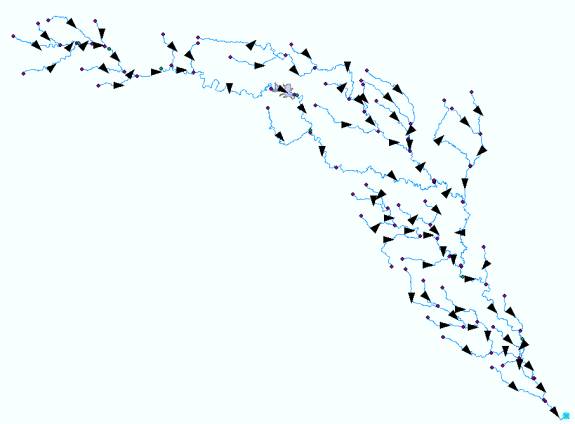
Your Network should look like the following diagram. If the network edges upstream of Canyon Lake are not shown with directions, it means that you need to build the Rf1guad shape file as a coverage and import that into the Arc Hydro geodatabase, rather than working with the Rf1guad shapefile imported into the geodatabase.
13. You can remove the display of arrows by clicking on Flow/ Display Arrows again or leave the arrows on as you wish.
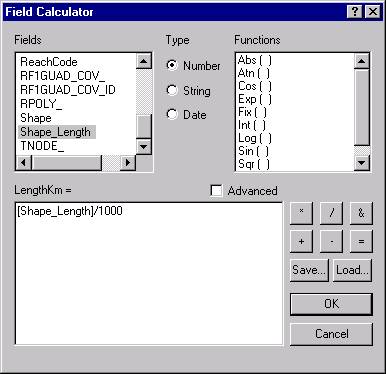
14. Now we are going to determine the values of the LengthKm attribute. Open the attribute table for HydroEdge, right click on the LengthKm field, and open the Field Calculator. Set the result equal to Shape_Length/1000 (Shape_Length is in meters)
15. Right click on HydroEdge and Open Attribute Table for HydroEdge. You will find LengthDown column with <null> values in it.
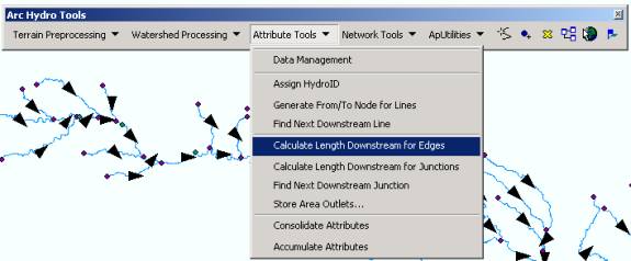
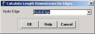
16. In the Arc Hydro Tools, go to Attribute Tools/Calculate Length Downstream for Edges. A message box appears warning the user that flow direction should be set before running this tool. We set flow direction in the previous steps, so click OK to proceed. Select HydroEdge for calculating Downstream Length and LengthKm for the Length Field. Click OK.
The values of downstream length from each edge will appear on the LengthDown column of the Attribute table. The table should look like this:
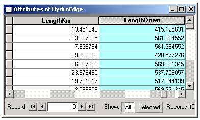
17. Close the Attribute Table of HydroEdge.
18. You will now calculate length downstream for HydroJunction. Right click on the HydroJunction layer and Open Attribute Table for HydroJunction. You will find LengthDown column with <null> values in it.
19. In the Arc Hydro Tools, go to Attribute Tools/Calculate Length Downstream for Junctions. A message box appears warning the user that flow direction should be set before running this tool. We set flow direction in the previous steps, so click OK to proceed. Select HydroJunction for calculating Downstream Length and LengthKm for the Length Field. Click OK.
The values of downstream length for HydroJunction will appear on the LengthDown column of the HydroJunction attribute table. Close the attribute table.
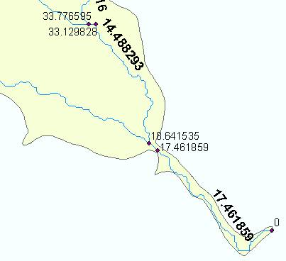
Now, let’s figure out what you have been doing. Right click on the HydroJunction layer. Under Properties, Select the Labels tab. Place a check in “Label Features in this layer”. Select LengthDown as the Label Field. Click OK. Similarly, set the Label Field of HydroEdge to LengthKm. You may alter the Text Symbol for the HydroEdge labels to Bold, to make the labels easier to distinguish from the HydroJunction labels. If you zoom in near the downstream outlet of the Guadalupe watershed, you should see something like the following diagram. The length downstream of the most downstream junction is 0 (this is where water flows into the Gulf of Mexico). The first river reach upstream of the outlet has length 17.72 km, so the LengthDownstream of the upstream junction is 17.72km, and so on for the succeeding upstream reaches and junctions. Pretty cool!!
III Find Next Downstream Junction:
Find Next Downstream Junction tool uses the network to find the next downstream
junction in a particular feature class, and assigns the HydroID of the
downstream junction to the NextDownID field in the upstream junction.
20. Right click on the HydroJunction layer and Open Attribute Table. You will find the NextDownID column with <null> values in it. We will use the Find Next Downstream Junction tool to populate this column.
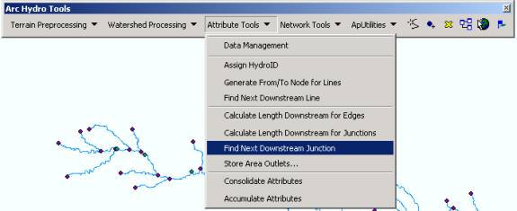
21. In the Arc Hydro Tools, go to Attribute Tools/Find Next Downstream Junction. A message box appears warning the user that flow direction should be set before running this tool. Click OK to proceed. Select HydroJunction and click OK. When prompted to check for spatially coincident junctions, click No. (Checking for spatially coincident junctions is an advanced topic. See Arc Hydro Tools documentation for details.)
The values of HydroID for the next downstream junction for each junction will appear in the NextDownID column of the Attribute table. You will find value of –1 for the most downstream junction in the network. If the tool does not find a downstream junction for a particular feature, it assigns a value of –1 to the feature’s NextDownID.
If you set the labels for HydroJunction to NextDownID and zoom to the basin outlet, you’ll find a display similar to the following:
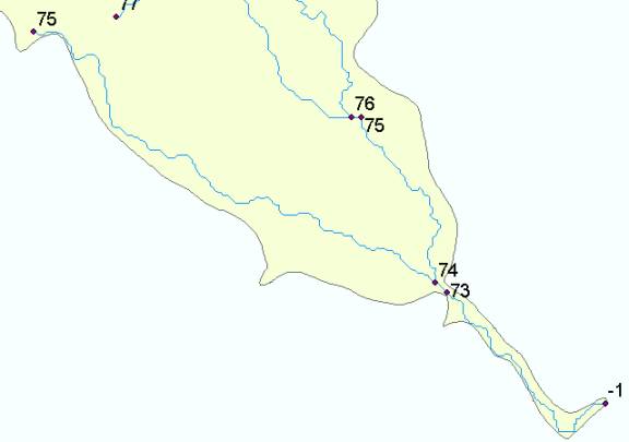
The most downstream HydroJunction has HydroID 73, which is the NextDownID of the next upstream junction (74). You can see that junction 75 is the NextDownID for two upstream junctions because it lies at a confluence in the river system.
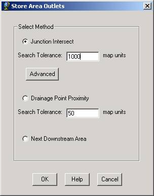
IV. Store Area Outlets:
The Store Area Outlets Tool locates outlet junctions for a set of areas. It writes the HydroID of the outlet to the JunctionID field in the area feature class. If a JunctionID field does not exist in the area feature class, one will be created for you. The junction feature class must have a HydroID field of type Integer.
Note that the Junction Intersect method does NOT create junctions at the intersection of the areas and the network for you. The tool assumes that this step has already been done using the Geoprocessing Wizard or by some other means.
If an outlet could not be found for a given area after the execution of all specified methods, then a JunctionID of –1 is assigned for that area.
22. Right click on Watershed and Open Attribute Table for Watershed. You will find the JunctionID column with <null> values in it. We will use the Store Area Outlets tool to populate this column.
23. In the Arc Hydro Tools, go to Attribute Tools/Store Area Outlets. In the Store Area Outlets dialog box select Junction Intersect as the method and set the Search Tolerance to 1000 map units. A message box appears warning the user that flow direction should be set before running this tool. Click OK to proceed.
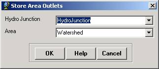
24. Select HydroJunction as the Hydro Junction Layer and Watershed as the Area Layer in the Layer dialog box. Click OK.
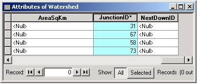
The tool will require a few seconds to calculate. The HydroIDs of the outlet junctions will be written in the JunctionID column in the Watershed attribute table.
The table should look like this:
You can inspect the watersheds and outlets manually to make sure that outlets were correctly assigned.
25. Close the attribute table.
V. Consolidate Attributes:
The Consolidate Attributes Tool summarizes values from an input feature layer to an output feature
layer. Consolidation operations include sum, max, min, count, average, median,
mode, standard deviation, and weighted average by field. We will use the Consolidate Attributes tool
to find the incremental drainage area for each HydroJunction. The incremental drainage area for a
HydroJunction is the area of the watersheds for which that HydroJunction serves
as the outlet junction. Outlets were
determined in Section IV: Store Area Outlets.
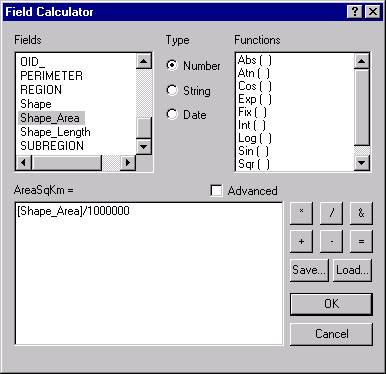
26. Lets populate the AreaSqKm attribute of the Watershed feature class. Open the attribute table for Watershed if necessary. Right click on the AreaSqKm attribute, and open the field calculator. Set the result for AreaSqKm to Shape_Area/1000000, as shown:
27. Right click on HydroJunction and Open Attribute Table for HydroJunction. You will find DrainArea column with <null> values in it. We will use the Consolidate Attributes tool to populate this column.
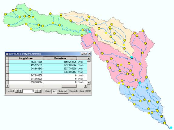
28. In the Arc Hydro Tools, go to Attribute Tools/Consolidate Attributes. The Consolidate Attributes dialog box appears. Select HydroJunction as the Target Feature Layer, and DrainArea as the Target Field. Select Watershed as the Source Feature Layer, and AreaSqKm as the Source Field. Select Sum as the Consolidation Type, and click OK. The completed dialog box is shown below. Click OK.
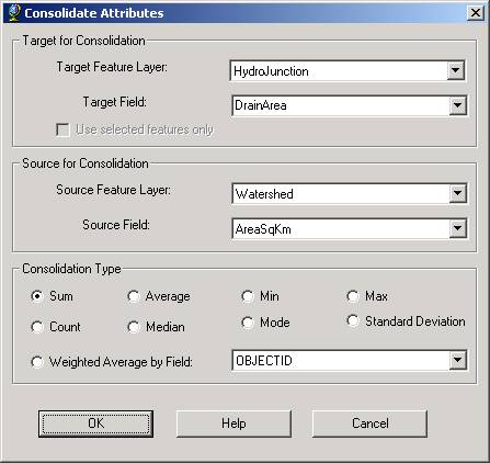
For each HydroJunction, the tool will find the Watersheds that drain to that junction (if any). The tool then sums the AreaSqKm values from those watersheds and assigns that value to that HydroJunction’s DrainArea. Thus, each HydroJunction now knows the AreaSqKm value of all Watersheds for which that HydroJunction serves as the outlet.
29. Inspect the attribute table of HydroJunction to verify that DrainArea values have been calculated. The outlet Junction for each watershed should have the drainage area of that watershed, while all other HydroJunctions should have a DrainArea value of zero.
30. Close the attribute table.
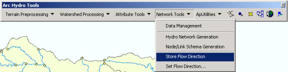
VI. Store Flow Direction:
The Store and Set Flow Direction Tools use the network to store or assign flow directions of edges. The tools work on a selected set of edges or the entire set if no edges are selected.
The Store Flow Direction Tool reads flow direction for edges from the network and writes those values to the edge attribute table.
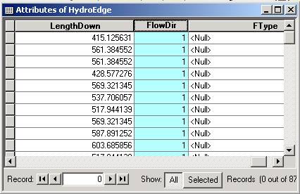
31. Right click on HydroEdge and Open Attribute Table for HydroEdge. Move to the FlowDir column in the Attribute Table. It will have <null> values in it. We will use the Store Flow Direction tool to populate this column.
32. In the Arc Hydro Tools, go to Network Tools/Store Flow Direction.
33. Select HydroEdge as Hydro Edge Layer to store flow direction in the dialog box. Click OK.
The values of Flow Direction will appear on the FlowDir column of the Attribute table. The table should look like this:
The Set Flow Direction tool assigns flow direction to edges. You may assign flow direction based on the selected esriFlowDirection constant, or you may assign flow direction based on values in a field in the edge layer. The values in the field must correspond to esriFlowDirection constants. The tool works on a selected set of edges or the entire set if no edges are selected. There is no need to use the Set Flow Direction tool in this exercise, since flow direction was already assigned using the Utility Network Analysis toolbar. The Set Flow Direction tool is most useful for setting flow direction in loops in the network. Edges in loops are assigned a flow direction of ‘Indeterminate’ by the Utility Network Analysis toolbar, so the Set Flow Direction tool can be used to give these edges a defined flow direction.
You have just applied all the Arc Hydro Tools!
To be turned in: What is the drainage area (km2) for
each of the four watersheds and for the drainage basin as a whole? Which feature classes are connected by
relationships in the data model? What
attributes are used as the key fields in these relationships?
GO to Home Page