Applying
the ArcGIS Hydro Data Model: Part 1
CE 394K GIS in Water Resources
University of Texas at
Austin
Fall 2001
Prepared by: Reem Zoun, Kristina Schneider, Tim Whiteaker, and David Maidment
Covered in Part 1
· Introduction to the ArcGIS Hydro Data Model and Arc Hydro Framework
· Computer and Data Requirements
· Procedure for the Assignment
1. View your data in ArcMap and ArcCatalog
2. Prepare your Data for Schema Application
D. Create Geodatabase and Import Data
Covered in Part 2
3. Applying the Schema
A. Add Schema Creation Wizard to ArcCatalog
B. Connect to the Repository
C. Selecting Features
D. Set Properties of Feature Classes
E. Create the Schema
4. Applying Tools
A. Add the Arc Hydro tools to ArcMap
B. Apply the Arc Hydro tools
I.
Assign HydroID
II.
Calculate Length Downstream
III. Find Next Downstream Junction
IV. Store Area Outlets
V. Consolidate Attributes
VI. Store Flow Direction
Introduction to the ArcGIS Hydro Data Model and Arc Hydro Framework
The ArcGIS Hydro Data Model (Arc Hydro) is an ArcGIS geodatabase model. It provides a standardized framework into which various types of water resources data can be loaded. In this manner the data forms an integrated water resources modeling and mapping database.
A geodatabase model is generated in a series of steps, beginning with the definition of classes and attributes in a Unified Modeling Language (UML) diagram created in the Visio 2000 drawing system. The second step is to export the diagram to a Microsoft repository format, which is an equivalent tabular structure, or schema, for loading into Microsoft Access (personal geodatabase) or other relational data servers (enterprise geodatabase). Finally, the data is imported into the Arc Hydro format by applying the schema to an ArcGIS geodatabase. Additional instructions for generating a schema in ArcCatalog can be found in the ArcGIS help files and in the book, ArcObjects Developer’s Guide (shipped with ArcGIS).
The ArcGIS Hydro Data Model stores data in four feature datasets, each corresponding to one of the main domains of the UML analysis diagram: Hydrography (map hydrography and associated data inventories), Drainage (drainage areas derived from digital elevation models or manually digitized), Channel (3-D profile and cross-section representation of stream channels), and Network (a geometric network representation of the connectivity of the surface water features of the landscape). Associated with these four feature datasets are a set of object tables for additional information, such as events defined on the river network, and time series of monitoring data.

To apply Arc Hydro, you simply apply the schema. One of the goals of this exercise is to apply a schema to a dataset. However, the Arc Hydro model, with four feature datasets, is a bit complicated if just used to demonstrate how to apply a schema.
The Arc Hydro Framework schema was created to provide a slimmed down version of the Arc Hydro model to provide practice in applying data models. Arc Hydro attempts to capture the majority of water resources data available, while Arc Hydro Framework's goal is to represent the most commonly used feature classes and relationships.
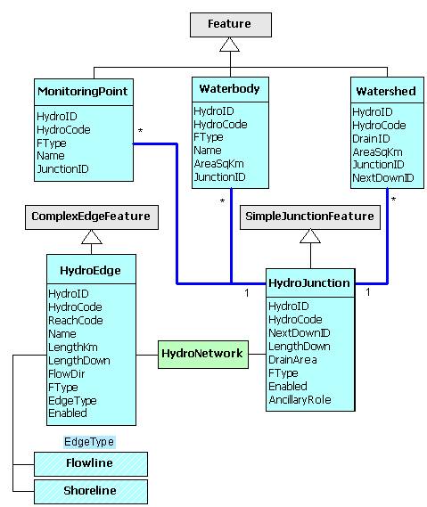
Arc Hydro Framework consists of one feature dataset called ArcHydro. The feature dataset contains only five feature classes: MonitoringPoint, Waterbody, Watershed, HydroEdge, and HydroJunction. MonitoringPoint represents point features from map hydrography and inventory sources used to collect water resources data. Waterbody represents area features from map hydrography. Watershed is a polygon feature class, which contains any subdivision of the landscape into drainage areas. HydroEdge and HydroJunction form a geometric network called HydroNetwork. The UML diagram below shows the relationships that create the schema.
Objectives of the Exercise
· To take regularly available geospatial data for hydrology and prepare it in the format needed for inclusion in a data model.
· To apply the Arc Hydro Framework schema to these data.
· To run a set of Arc Hydro tools to fill in the attributes contained in the schema.
In this exercise, you’ll learn editing skills for linear and areal features, and also how to create new lines and polygons as part of existing feature classes.
Computer and Data Requirements
· ArcGIS 8.1
· 35 MB of disk space
Data Files:
|
ArcHydroFrameworkSchema.mdb |
MS Repository for Arc Hydro |
|
Albstat Shapefile |
Point shapefile which contains gaging stations |
|
Rf1guad Shapefile |
Line shapefile showing the path of the river. |
|
Hucguad Shapefile |
Polygon shapefile representing watersheds derived for the Guadalupe basin. |
|
CreatePolyFromLines.txt |
VBA script for creating polygons from closed polylines |
These files are attached to this exercise as ArcHydro.zip.
Procedure for the Assignment
(1) Open ArcMap.
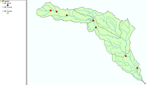
(2) Navigate to the directory with your data. Add the Albstat, Rf1guad and Hucguad shapefiles to the data frame. Explore the dataset by looking at the attributes for each class and visualizing them separately. These are the same files that you prepared for the Guadalupe Basin in exercise 2 of the course.
(3) Close ArcMap, you don’t need to save the data.
2.
Prepare your Data for Schema Application.
The Arc Hydro Framework schema contains 5 feature classes and at present we have data for only 3 of them: MonitoringPoint (Albstat.shp), Watershed (Hucguad.shp) and HydroEdge (Rf1guad.shp). In this part of the exercise, we are going to create the data for the other two feature classes, Waterbody and HydroJunction. The first thing we’ll do is to create a centerline through Canyon Lake.
A. Create Centerline
(1) Open ArcMap and add ‘Rf1Guad’ shapefile to your dataframe.
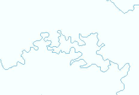
(2) Zoom into the area where the Guadalupe River goes around Canyon Lake to show the shape of the reservoir. We are going to create a centerline through Canyon Lake to form a complete network for Guadalupe River.
Canyon Lake
(3) Go to Tools/Editor Toolbar and the Editor toolbar will appear. On the Editor toolbar go to Editor/Start Editing.
(4) Go to Editor/Snapping and the Snapping Environment dialog will appear. Click all the options on for Rf1guad. It should appear as the dialog below after you have turned them on.
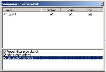
(5) Close the Snapping Environment dialog.
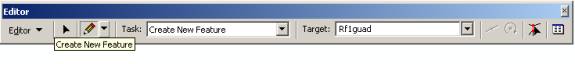
(6) Zoom into the Canyon Lake area and click on the Create New Feature icon on the Editor Toolbar (the little pencil).
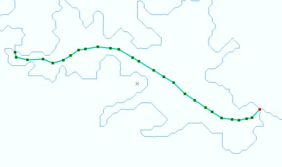
(7) Snap at the intersection of Guadalupe River and the reservoir and the continue clicking through the middle of the reservoir to crate a centerline. When you reach the end, double click. You should end up with a centerline in the middle of Canyon Reservoir. Note: If you cannot create a centerline because the cursor always snaps to the boundary of the lake, try decreasing the snap tolerance by clicking Editor/Options… and adjusting the Snapping tolerance.
(8)
Use the Editor/Save Edits to save the edits that you’ve
made. If you don’t like the centerline
you created, use Editor/Stop Editing to terminate the editing session
and do not Save Edits, and then restart the Edit session and redo the
centerline. To modify an existing
feature without retracing it, use Task: Modify feature in the toolbar
shown above and use the ![]() next to the Create
New Feature icon to select and edit the features you want to alter.
next to the Create
New Feature icon to select and edit the features you want to alter.
B.
Create Waterbody
Now we are going to take the lines that trace the shoreline of Canyon Lake and make them into a polygon to form a Waterbody.
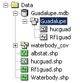
(1) Go to ArcCatalog, create a new geodatabase called Guadalupe.mdb, and import into it the shapefile hucguad.shp, naming the feature dataset Guadalupe, and then import rf1guad.shp into this feature dataset. If you go to the Properties of the Guadalupe feature dataset, you’ll see that it has the albers projection of the Guadalupe data that you used in exercise 2 earlier in the course. The hucguad.shp file was imported here to make sure that the extent of the feature dataset was large enough to cover all the region of interest. It’s really the rf1guad river reaches that we are interested in working with.
Next we are going to create the Waterbody in ArcMap. Because only one ArcGIS application can access a geodatabase at a time, we must first close ArcCatalog.
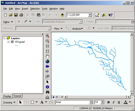
(2) Close ArcCatalog. Open ArcMap and add Rf1guad from the Guadalupe geodatabase that you just created.
(3)
Click on the Edit ![]() button on the editor
toolbar. Select the shorelines of the Canyon Lake by clicking on them using
shift key. Use the Editor/Merge command to merge the two shorelines into
a single feature.
button on the editor
toolbar. Select the shorelines of the Canyon Lake by clicking on them using
shift key. Use the Editor/Merge command to merge the two shorelines into
a single feature.
(4) Save edits and Stop editing.
Now we add some Visual Basic code to convert the polylines forming Canyon Lake into a polygon feature class.
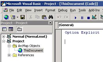
(5) Make sure that Rf1guad is the only layer in the map. Open the Visual Basic Editor by clicking Tools/Macros/Visual Basic Editor. The VBA environment window for ArcMap opens up.
(6) Open the code window for ThisDocument by expanding the project window items until ThisDocument appears, and then by double clicking on ThisDocument. (You may or may not have the words “Option Explicit” at the top of the code window. The code that we will use will work either way.)
(7) Open CreatePolyFromLines.txt from the ArcHydro.zip file included with this exercise. Make sure the Word Wrap option IS NOT checked. This option can usually be found under the Format menu. Note: For helpful macros and extensions (including CreatePolyFromLines), look in arcexe81\ArcObjects Developer Kit\Samples.
(8) Copy all of the text in CreatePolyFromLines.txt, and paste it into the code window. If you have the words “Option Explicit” at the top of the code window, paste the CreatePolyFromLines code below the words “Option Explicit”.

(9) Close the VBA window.
(10) Now it’s time to run the macro. In ArcMap, click Tools/Macros/.
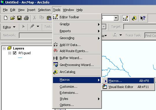
(11) In the Macros window, highlight ClosedLinesNewFC and click Run.
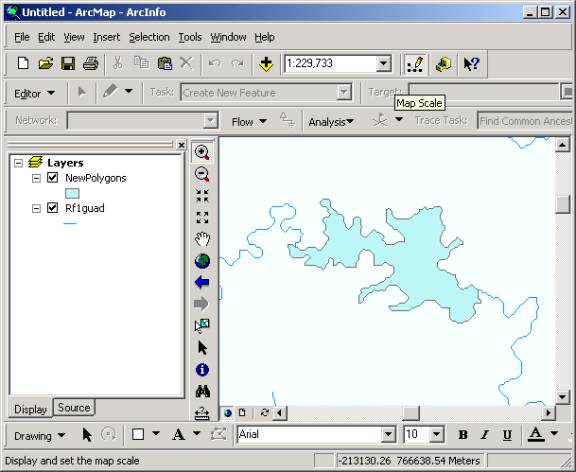
A new feature class called NewPolygons is created in the Guadalupe geodatabase and added to ArcMap.
Now that the Waterbody has been created, we can delete the shorelines of Canyon Lake.
(12) Clear any selected features and turn off NewPolygons.
(13) Go to Editor/Start Editing. Set the Task as Modify feature and Target as Rf1guad on the Editor Dialog box. Select the canyon reservoir shoreline and delete it. This creates a simple network through the lake rather than parallel paths around its edges.
(14) Go to Edit/Save Edits and Stop Editing. Exit ArcMap. You don’t need to save changes.
Now, we are going to create junctions for our network using the geometric network builder.
(1) Open ArcCatalog.
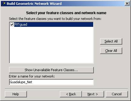
(2) In the Guadalupe feature dataset, Create a new geometric network, Building with Existing Features, Select Rf1guad as the feature class and Guadalupe_Net as the network to be created. Do not use Complex Edges in the network. Do not snap features. Do not assign weights to the network.
Once you’ve got the network created, you’ll see that you’ve added a new feature class called Guadalupe_Net_Junctions, which is created during the network building process to link the lines in the Guadalupe network. These are called ESRI Generic Junctions. We are now going to transform them into Junctions for use in the Arc Hydro data model.
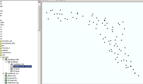
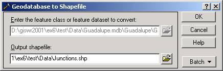
(3) In ArcCatalog, right click on Guadalupe_Net_Junctions and use Export/Geodatabase to Shapefile to create a new shapefile called Junctions.shp.
(4) Export the NewPolygons feature class to a new shapefile called Waterbody.shp.
D.
Create Geodatabase and Import Data
When applying the Arc Hydro schema, it works best when you have a geodatabase with feature classes already in it with the correct class names. So lets create that now.
(1) Open ArcCatalog. Right click on the data folder, press New/Personal Geodatabase. Call the new geodatabase ArcHydro.
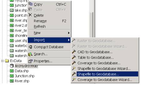
(2) Now, you will import your shapefiles into the geodatabase. Right-click on your geodatabase and press Import/Shapefile to Geodatabase.
You will be importing all of your shapefiles. First, you must navigate your data folder in the Input shapefile box. Choose the hucguad shapefile, since this file has the largest extent. Type in ArcHydro as the name for your new feature dataset and Watershed as the name of new feature class. You will repeat the above process until the remaining shapefiles are added. It is important to note that each feature class should have the name assigned to it in Arc Hydro Framework. See the table below for the corresponding information.
|
Shapefile |
Arc Hydro Framework Feature Class |
|
hucguad |
Watershed |
|
albstat |
MonitoringPoint |
|
Junction |
HydroJunction |
|
Rf1guad |
HydroEdge |
|
Waterbody |
Waterbody |
E.
Create Geometric Network
(1) The next step is to create your geometric network, HydroNetwork. Right-click on the feature dataset Arc Hydro and press New/Geometric Network. Press Next on the first screen and then select Build a geometric network from existing features on the second screen. In third screen, select the HydroJunction and HydroEdge files to be part of the network.

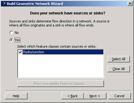
Also, name the network HydroNetwork. This is an important step since the schema will only accept a network with the same name as in the model description. Click No to enable all features in the network on the fourth screen. Click Next. You will be asked if your network has complex edges, select Yes and HydroEdge. Click Next. In the sixth screen, select No since your features do not need to be snapped and click Next. You will be asked if your network will have sources or sinks, in the seventh screen. Click Yes and select HydroJunction.
Press Next. You will be asked if you would like to assign weights to the network, answer No and click Next. Finally, press Finish to create the geometric network.
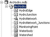
Your geodatabase should look like this.
In summary, the important factors to remember when preparing your data for schema application are the following:
- Assign the appropriate Arc Hydro Framework name to your feature datasets, feature classes, and feature attributes allows for automatic recognition by the schema creation wizard.
- Create the network (HydroNetwork) with HydroEdge and HydroJunction. HydroEdge will be a complex edge and HydroJunctions will contain sinks. Each point in the HydroJunction does not have to be a sink but all HydroJunctions will have the option of becoming a sink.
Ok, super duper, you’ve now created your input data sets!
In the next part of the exercise, we’ll apply the Arc Hydro Framework schema and the Arc Hydro tools.
Note: In some situations, it’s better to only import generic junctions that have some significance into the HydroJunction feature class, while leaving the remaining junctions as generic junctions. However, in this exercise, no such distinction is made between generic junctions; therefore, all generic junctions were loaded into the HydroJunction feature class.